D2 Laser Servo
- High-bandwidth Laser Current Feedback
- Auxiliary Feedback to temperature or PZT for long-life locks
- Double Integrators to eliminate drift
- Smooth Lockup
- Frequency Jumping and Integrator Blanking
- Internal Ramp Generator
- Highly adjustable PID corner settings
- Lock Guard lock recapturing
- Ramp Centering
- Optional Peak Locking (-PL)
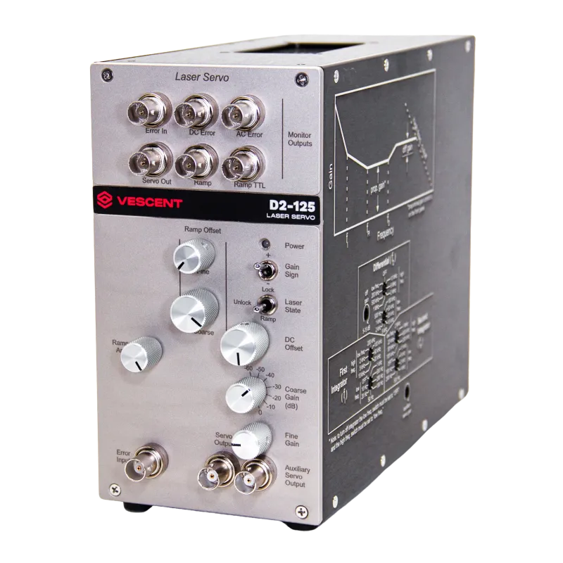
The D2-125 laser servo was designed for low-noise servo control of lasers and other experimental systems. The PI2D loop filter, with two-stage integral feedback, provides tight locking to cavities and atomic/molecular transitions. The D2-125 provides full user control over the loop-filter parameters, which enables servo-loop optimization for a wide variety of plants, such as current tuning, acousto- and electro-optic modulators, voice coils, piezo actuators, etc.
Lock Guard auto relocking function is included with every D2-125 Laser Servo. Lock Guard detects when the servo loop filter has gone out of lock and automatically tries to recapture lock. Lock Guard monitors the servo output, and when it detects an Unlock Point (a fast change in the servo output; see arrow on the red trace), it disengages the servo and returns the output to the last known valid value. Lock Guard waits for the Hold Time (shorter interval on blue trace) and then re-engages the lock. Lock Guard waits for the Settle Time (longer interval on blue trace), and if it detects that the system is still out of lock, it will reset the servo output again. The Lock Guard control parameters, Unlock Point and Hold & Settle Times are all user adjustable for maximum flexibility and optimized performance.
The D2-125 has the flexibility to optimize its performance for your experiment. The Peak Lock option provides an adjustable-amplitude 4 MHz dither which can directly modulate a diode laser or drive an external modulator. The incoming error signal is then demodulated at this same 4 MHz (with adjustable phase). The resulting first-derivative error signal allows the user to lock a laser to the peak of the error feature instead of the side without the implementation of an external modulator and lock-in amplifier, simplifying and reducing the cost of many experimental configurations.
General
| Parameter | Value | Units |
|---|---|---|
| Input and Output Impedance | 501 | Ω |
| Output Voltage (main and aux) | ±10 | V |
| Input Voltage Noise2 | <5 | nV/√Hz |
| DC Offset Range | ±500 | mV |
| Error Input Max Amplitude | ±500 | mV |
| Bandwidth3 | >10 | MHz |