A Story of Optical Frequency Combs
Frequency combs are wondrous devices with enabling utility across multiple applications, including quantum computing, pollutant sensing, next-generation atomic clocks, microscopy, RADAR, and many more. The importance of frequency combs is such that they contributed to the 2005 Nobel Prize in Physics, shared by Jan Hall in Colorado and Ted Hänsch in Munich. But what exactly is an optical frequency comb?
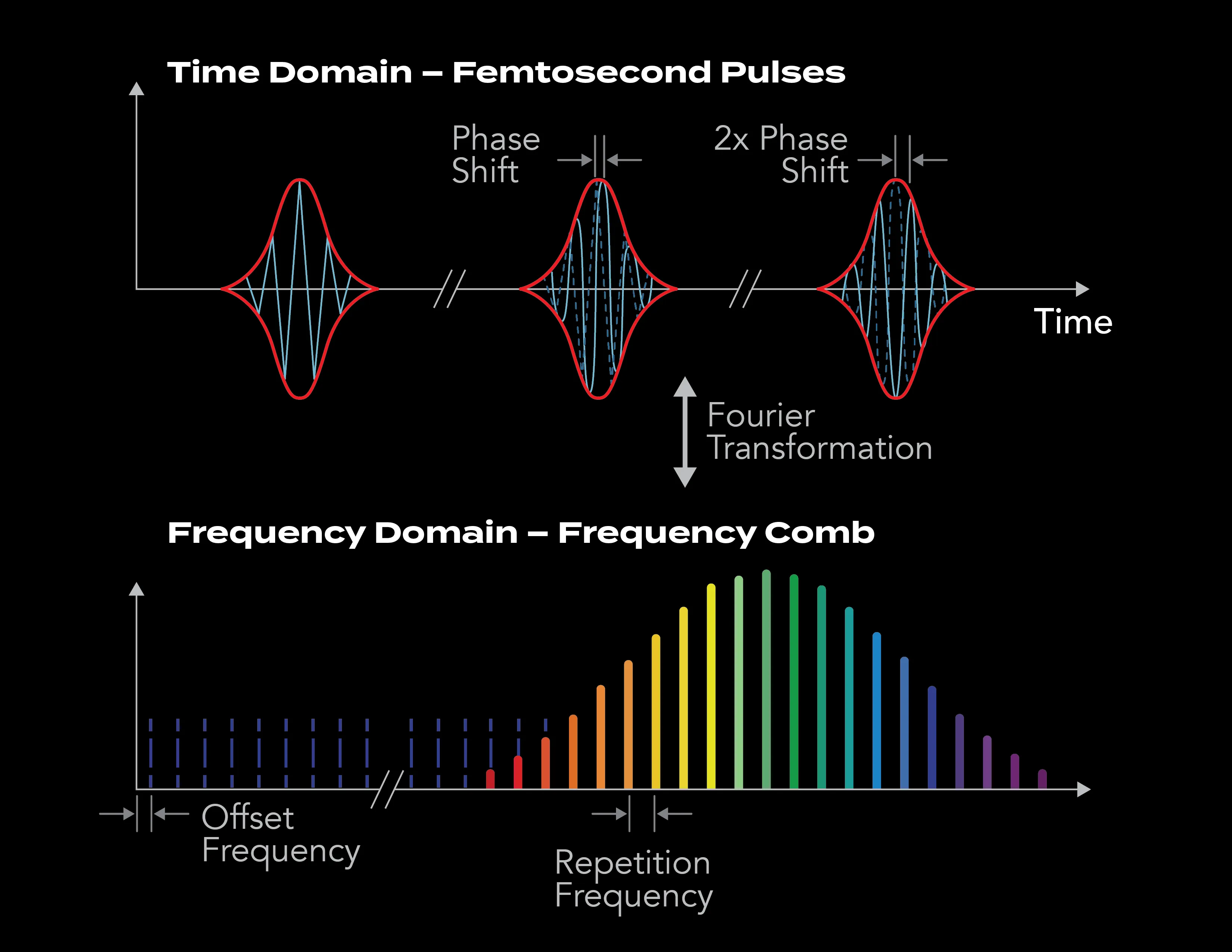
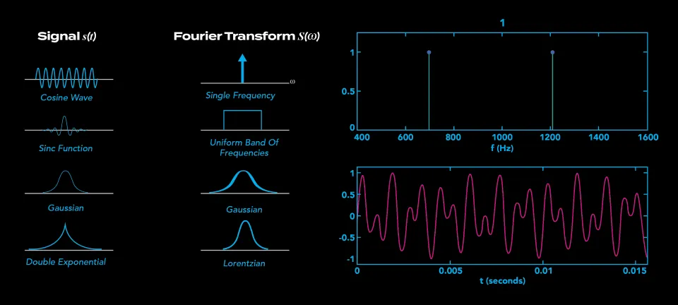
At its simplest level, any pulsed laser with a regular repetition rate can be called a comb. If one takes the Fourier transform (explained more later) of the time domain pulsed laser, you get a spectrum of regularly spaced continuous wave (CW) lasers. This spectrum looks like a comb, with each individual CW laser as one of the “teeth” of the comb. We refer to these “comb teeth” as “comb modes.” The separation between the comb modes in the frequency domain is given by the repetition rate of the laser pulses in the time domain; e.g., a 200 MHz temporal repetition rate pulsed laser will result in a comb spectrum with modes separated by 200 MHz in frequency.
So, is every pulsed laser actually a frequency comb? There is debate about what actually constitutes an “optical frequency comb.” From the simple picture presented above, indeed any pulsed laser with a repetition rate that is higher/faster than the frequency width of the comb modes could be classified as a comb; i.e., in the frequency domain the spectrum “looks like a comb.” Many people use this as a definition of an optical frequency comb. By this thinking, optical frequency combs have been around since the 1960s when sufficiently high rep-rate Q-switched lasers were first demonstrated. This, however, is not the definition we use at Vescent. From our perspective, the pulsed lasers from the 1960s were not combs; to be a comb, it takes something more. Specifically, to turn “just” a pulsed laser into a frequency comb took a breakthrough that is often referred to as “self-referencing,” which we will describe later. Indeed, this self-referencing breakthrough was deemed so important that in 2005 it was recognized as an important element of the Nobel Prize in Physics. These self-referenced combs are what Vescent manufactures and sells.
A true self-referenced, fully stabilized optical frequency is an amazingly enabling device. In such a device, the frequency of the individual comb modes can be used as a “ruler” to precisely measure light, or to transfer stability from an atom or optical cavity to other lasers, or to remotely detect pollutants, or be the metric against which other lasers are stabilized and controlled to enable applications such as quantum computers.
The basic frequency comb equation is beautifully simple:
where n is a specific comb mode, frep is the fixed repetition frequency or space between modes, and fCEO is the offset frequency.
Before getting into frequency comb details, let’s zoom out a bit and consider optical frequency combs in a fuller historical context.
The Vescent Team is part of the proud and ancient lineage of tool makers. It is an understatement that human-made tools have changed the world many times over. A particularly pertinent tool example is the oscillator—something that provides a signal that repeats at a constant rate (or constant period of 1/rate). An oscillator plus a counter—something that counts the oscillations—is a clock. This combination of oscillator plus counter has arguably been one of the most important tools in human history. Let me give an historic example.
The Challenge of Marine Navigation
Once humans built ships capable of transoceanic travel, the need for navigation beyond the sight of land became essential. Celestial navigation provided latitude; the positions of the stars in the sky change as one moves from the equator to the poles. Longitude, on the other hand, was much trickier. One approach is a maritime, “ship deployable” clock. Essentially, the time of day that celestial objects emerge on the horizon varies as longitude changes. The sun rises in England before it rises in Ireland; this is why the world has time zones. If one had a “good-enough” clock that could work on a ship, this could provide longitude. Unfortunately for 18th century mariners, the best clocks were pendulum clocks. These simply did not work on a rocking ship.
As a famous example of the need for improved navigation, the Scilly Naval Disaster of 1707 resulted in the deaths of around 2,000 sailors! This problem needed to be solved.
The Harrison Clocks
John Harrison (3 April 1693 – 24 March 1776) was an English carpenter and clockmaker who invented the marine chronometer, a long-sought-after device for solving the problem of calculating longitude while at sea.
Harrison’s innovations (there were many), and the commercial products that came from his innovations, revolutionized navigation and greatly increased the safety of long-distance sea travel. This advancement enabled the British to project power globally with its navy and to control global trade, which in turn led to the British Empire, the largest empire in history on which “the sun never set.” It is arguably why people in the US speak English and why Greenwich mean time is measured from, well, Greenwich, England. Technology and tools have geopolitical impact. A clock that was smaller and could be deployed (in this case at sea), changed the world!
The Harrison Clocks improved with each iteration, decreasing in both size and weight:
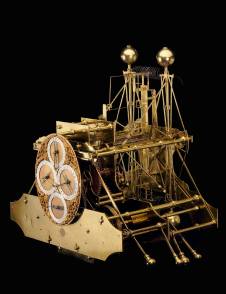
H1
CHRONOMETER | 1730 – 1735
- Height:63 cm
- Width:70 cm
- Depth:45 cm
- Weight:34 kg
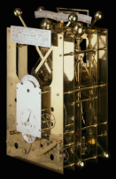
H2
CHRONOMETER | 1737 – 1739
- Height:66 cm
- Width:46 cm
- Depth:23 cm
- Weight:39 kg
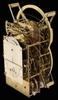
H3
CHRONOMETER | 1740 – 1759
- Height:59 cm
- Width:23 cm
- Depth:23 cm
- Weight:27 kg
H4
CHRONOMETER | 1755 – 1759
- Height:13 cm
- Width:12 cm
- Depth:6 cm
- Weight:1.45 kg
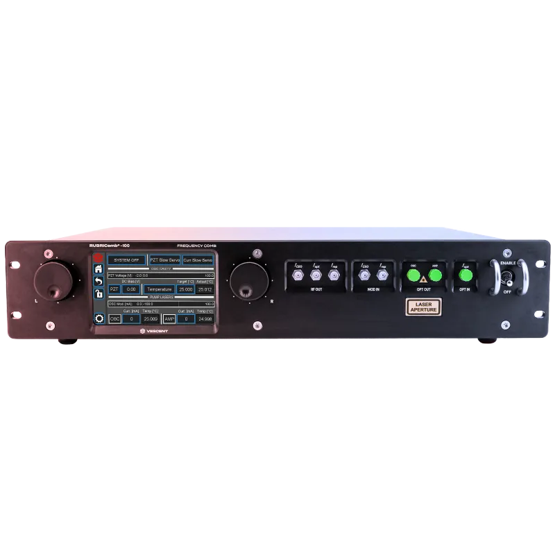
Vescent Frequency Combs
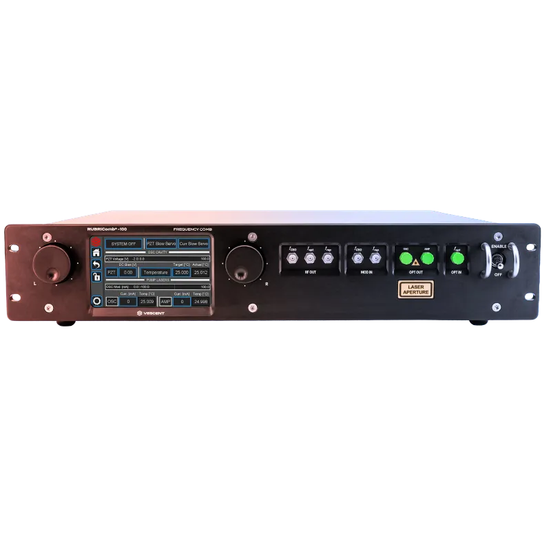
Vescent’s commercially available RUBRIComb® is a fully stabilized, environmentally robust optical frequency comb, up and running in 30 minutes and built for high-performance operation in the field. The Vescent team has compiled this brief introduction to frequency combs and how Vescent fits into the story.
Frequency Combs & How Vescent Fits
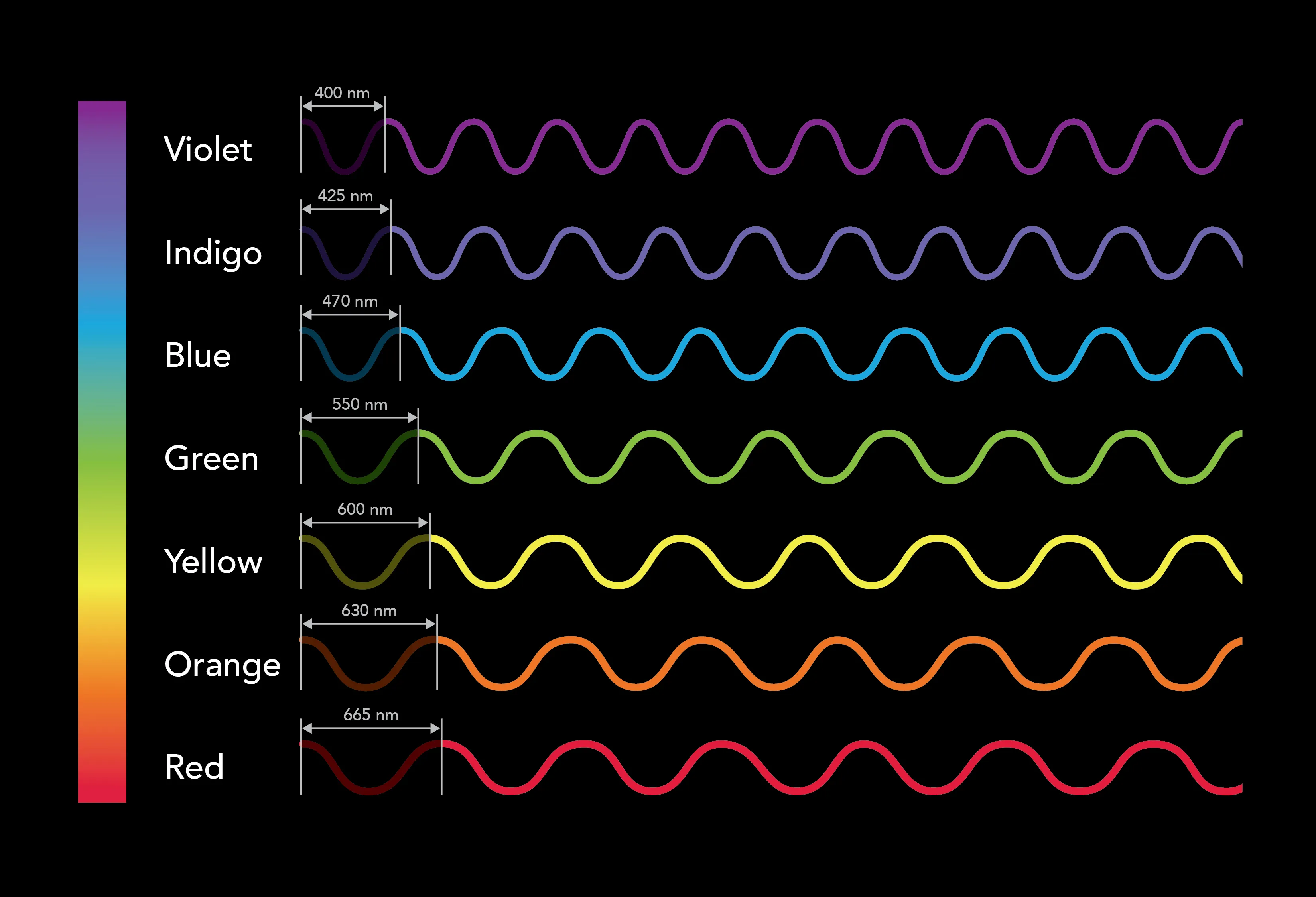
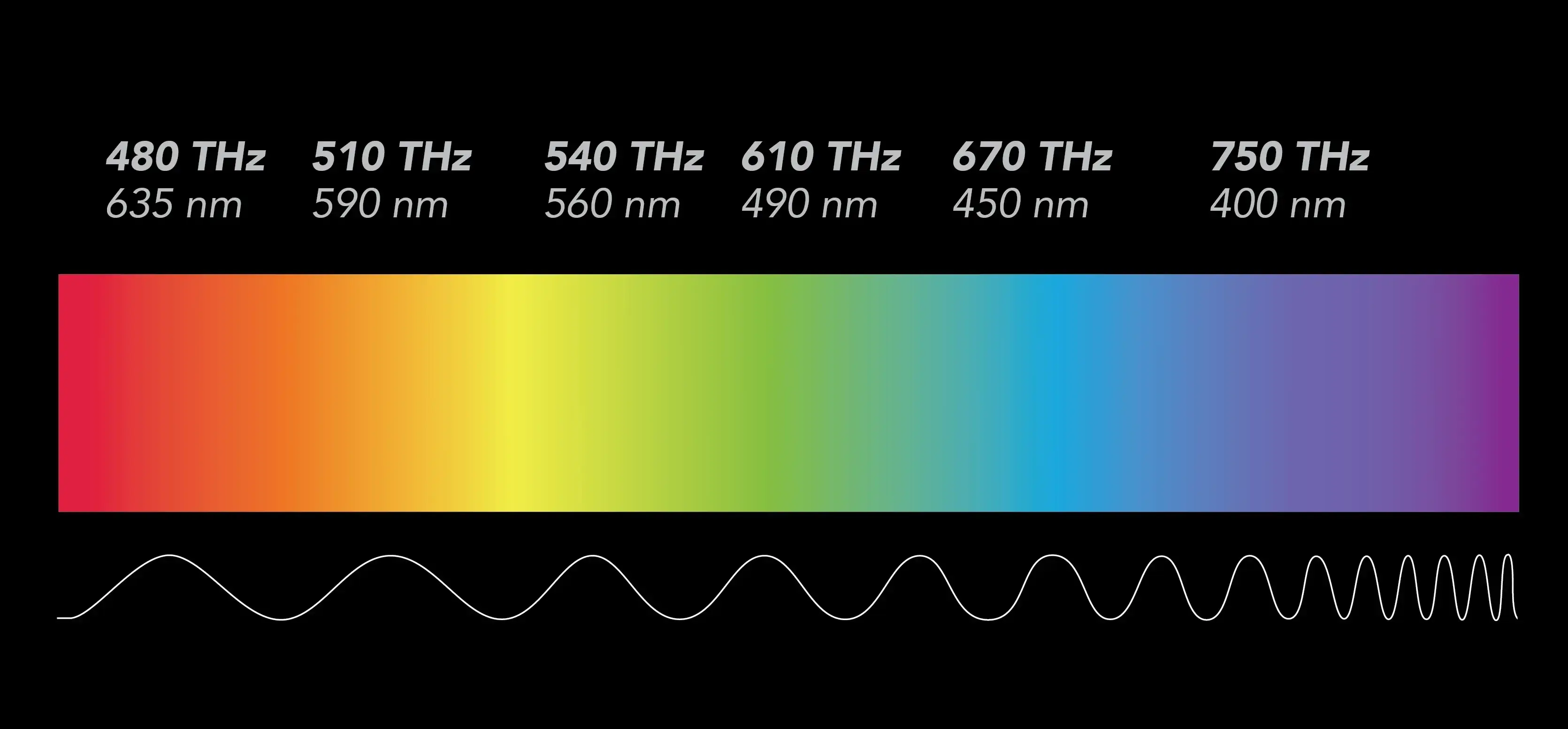
How does Vescent fit into this story? And again, what the heck is a frequency comb? As discussed above, a frequency comb is a special type of pulsed laser and instead of emitting light at a single narrow-band frequency as a “typical” continuous wave laser does, a frequency comb emits multiple frequencies at evenly spaced intervals, i.e., the “comb.” Remember, the frequency (or wavelength) of the light tells you the color.
Colors in the Spectrum
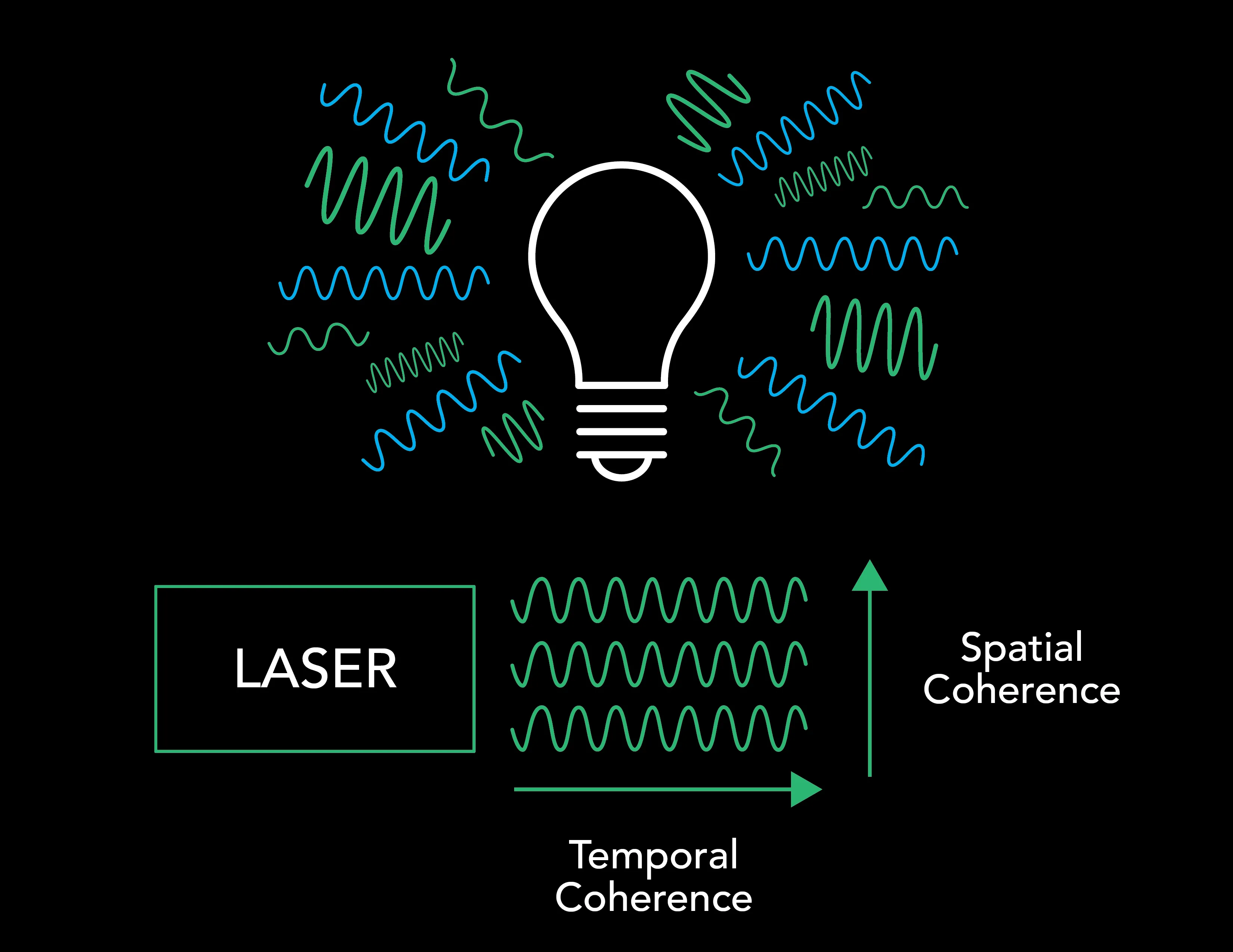
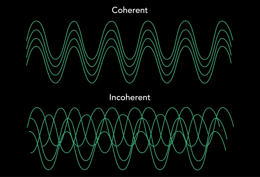
Also remember, a differentiating property of laser light (as opposed to, say, light from a flashlight) is a thing called coherence. There are two broad types of coherence: temporal and spatial.
With temporal coherence, the light waves are all in phase and at the same frequency/color. Stated simply, all of the photons have the same energy.
With spatial coherence, all the light waves are traveling in the same direction. A spatially coherent light-beam can be focused to a tight spot or collimated to transmit over a large distance with minimal divergence (spread).
In typical optical systems, one can’t get one type of coherence without also having the other. For example, broad spectral coverage (lots of colors) can be provided by sources such as a glowing hot piece of metal (glow-bar) or a light bulb filament. However, one can’t focus the light from a glow-bar or Edison filament into a tight spot, or transmit the light with minimal divergence (spread) over a large distance. One either has coherent beams (limited color spread) that can be transmitted over large distances, or one has many colors (large spectral coverage) in incoherent beams that do not transmit or focus well. The magic of the frequency comb is that it can provide the best of both worlds!
Fourier Transform
(one of Vescent CEO Scott Davis’s favorite equations!)
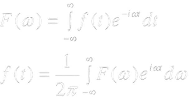
In the introduction, we talked about Fourier transforms. The Fourier Transform converts between domains. Pertinent to this discussion, the Fourier transform can be used to convert from the time domain to the frequency domain, and vice versa, providing a way to do spectral (frequency) analysis of a time-varying signal. This set of equations is arguably one of the most important in all of physics!
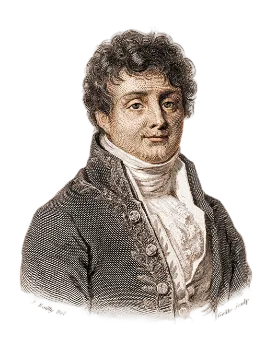
Jean-Baptiste Joseph Fourier
Born: 21 March 1768 · Auxerre, Kingdom of France
Died: 16 May 1830 · Paris, Kingdom of France
Continuous Wave (CW) & Pulsed Lasers
The output of an ideal continuous-wave (CW) laser is relatively easy to imagine. It may be viewed as a beam of light with a near-constant power and a near single-color (frequency). A red laser pointer is a common example.
One may create a CW laser by placing an optical gain media in between two mirrors pointed at each other. As the light bounces between the two mirrors, it passes through the gain media and is amplified. Through the beauty of quantum physics, this gain is created through a process called “spontaneous emission.” Indeed, the very word laser is an acronym (Light Amplification by Stimulated Emission of Radiation), and the spontaneous emission process requires that the emitted and stimulating photons are all in phase, i.e., temporally coherent.
The output of an ideal pulsed laser is also conceptually quite simple. It may be viewed as a beam of light that comes in short bursts, or pulses.
There are many ways to create a pulsed laser. Some are conceptually quite simple, such as choosing when to turn it on. One common way to create a pulsed laser with a steady repetition or pulse rate is through a process called mode-locking. An attractive and widely used technique is passive mode-locking with a saturable absorber inside the cavity. In a mode-locked laser, a large collection of laser cavity modes oscillate in-phase to constructively add up to a laser pulse bouncing back and forth between the mirrors. The pulse rate, i.e., the repetition rate frep, is determined by the round-trip time for the light to bounce between the mirrors.
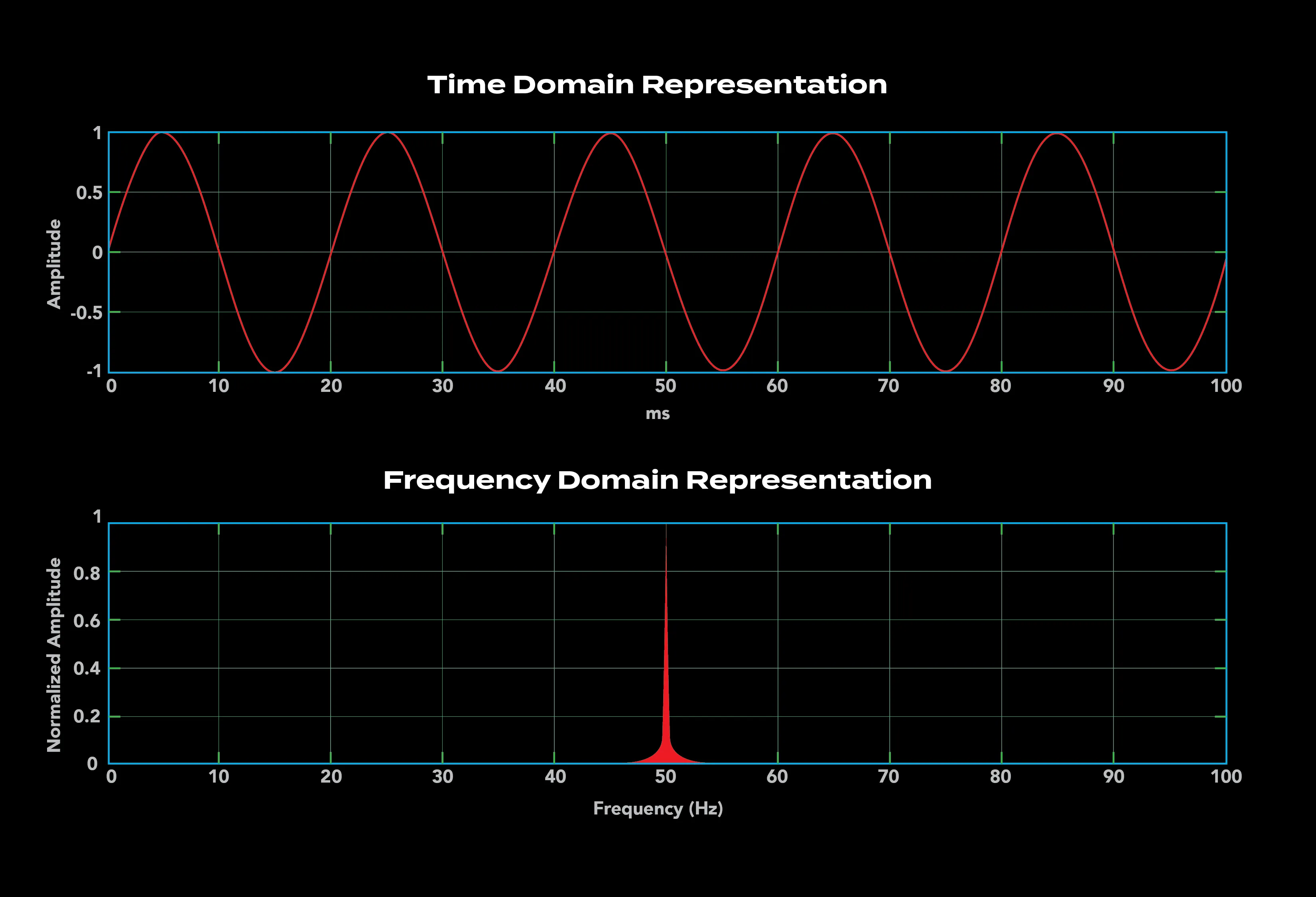
As mentioned, in the time domain, a pulsed laser is quick little bursts of light. In the frequency domain, a pulsed laser is a series of CW lasers with repetition rate frep being the frequency spacing. The problem with a free-running pulsed laser is that the exact location of the comb teeth or modes is not fixed.
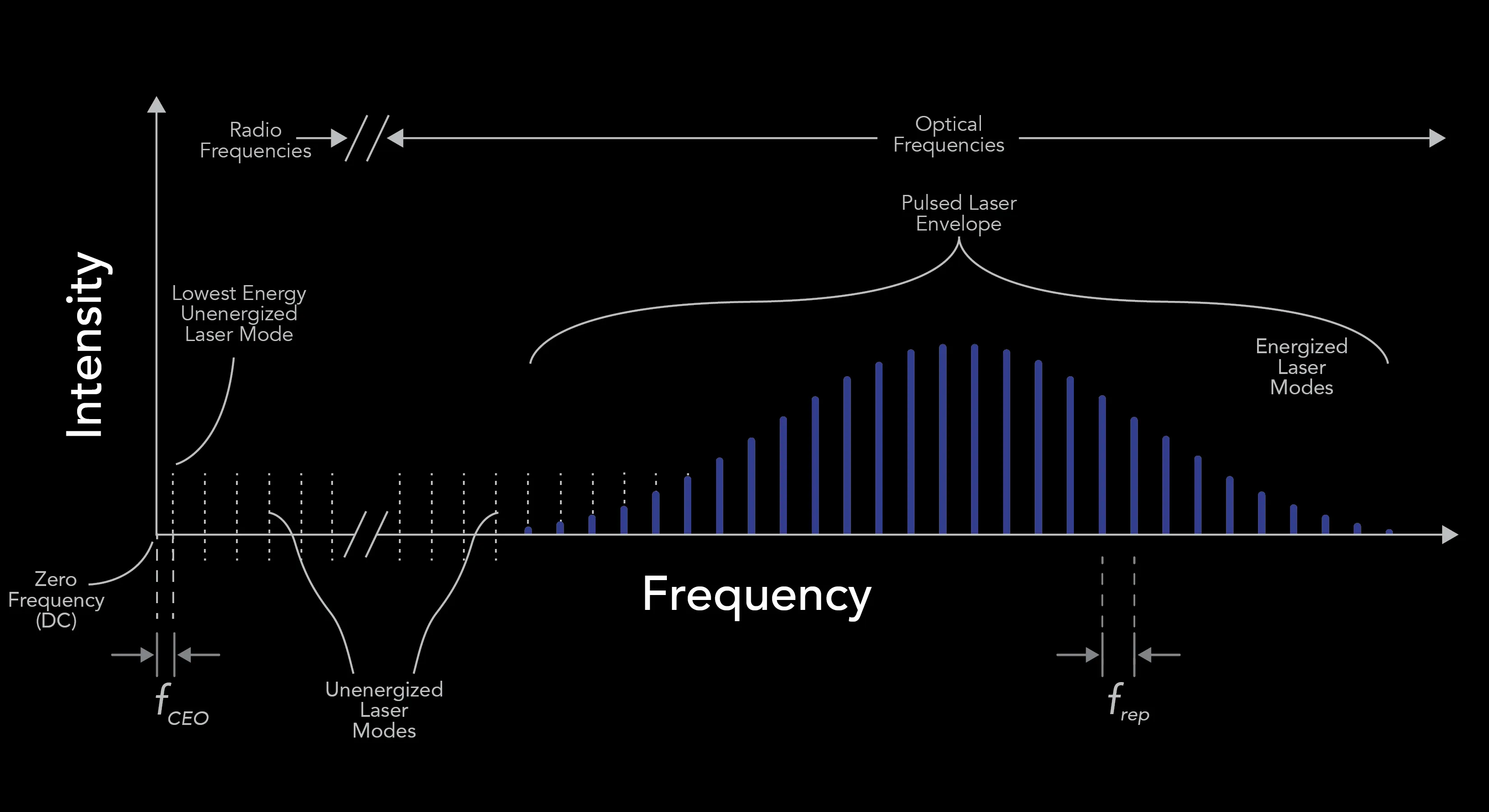
The solution is to self-reference the comb—to control both frep and fCEO. If you start at one cavity mode in the optical domain and start progressing down toward lower frequencies, in steps of frep, one will eventually get down into the radio frequency domain. If you keep stepping down, you will reach a point that is less than frep away from DC or 0 Hz. This offset, from 0 Hz to the lowest frequency comb mode (note, there is no light populating these low frequency comb modes) is referred to as either fCEO or f0.
These two key parameters from the simple comb equation are quite intuitive. Altering fCEO shifts the whole comb to the left and right in the frequency domain. Altering frep changes the spacing between the comb modes and can be thought of as a “breathing” of the comb.
To measure frep, one just directs the comb light (remember it is a pulsed laser) onto a photodiode (assuming your cavity is not too small; i.e., frep is not too large). For fiber-based frequency combs that Vescent typically builds, frep can be in the 100s or even 1000s of MHz.
Measuring fCEO is more difficult; this is where a true comb or a self-referenced comb differs from just a pulsed laser. This innovation of self-referencing is what merited the Nobel prize! A common way of self-referencing (and what we do at Vescent) is to utilize nonlinear optics. One of the wonderful properties of nonlinear optics is their ability to combine and subtract photons of certain colors and emit photons at new colors. This is described in the four steps below:
- The spectral breadth of the comb needs to span an octave. This means that the reddest tooth is half the frequency of the bluest tooth. This is just like an octave in music! This is done by sending the comb light, i.e., the laser pulse train, into a nonlinear optic (e.g., nonlinear fiber, a nano-photonic waveguide, or other nonlinear device). Photons from each of the comb modes combine with photons from other comb modes to create photons of new colors.
- This octave-spanning light is then sent into another nonlinear optic such as a PPLN (periodically poled lithium niobate) crystal to double the red modes to make them be the same color as the blue modes. Note, the poling period of the crystal selects a set of comb modes. The net result, for sum-frequency, is that a group of comb modes at the red part of the envelope are doubled in frequency, so that they overlap in frequency with a group of comb modes at the blue part of the envelope.
- One may then spatially overlap these doubled red-modes with the blue modes using conventional optical techniques. When this overlap is measured on a photodiode, one measures the “beat note” or frequency difference between the blue modes and the doubled red modes. This technique is called heterodyning. The heterodyne beat note will be in the RF and therefore can be detected on a photodiode. Through some relatively simple math of the basic comb equation, this provides a measure of fCEO.
- One may then electronically lock this beat note to an electronic RF oscillator, which in turn locks fCEO by feeding back to properties in the laser that tune fCEO. Similarly, frep can be locked to an RF oscillator, or one of the comb modes can be locked to an atomic or molecular transition or a transmission of a high finesse cavity. One then has a fully self-referenced and stabilized optical frequency comb, which enables amazing applications!
By stabilizing fCEO and frep, we also stabilize the phase of the pulses. All of the comb modes are phase coherent. By stabilizing fCEO and frep we also have a “ruler” that can measure in the optical domain.
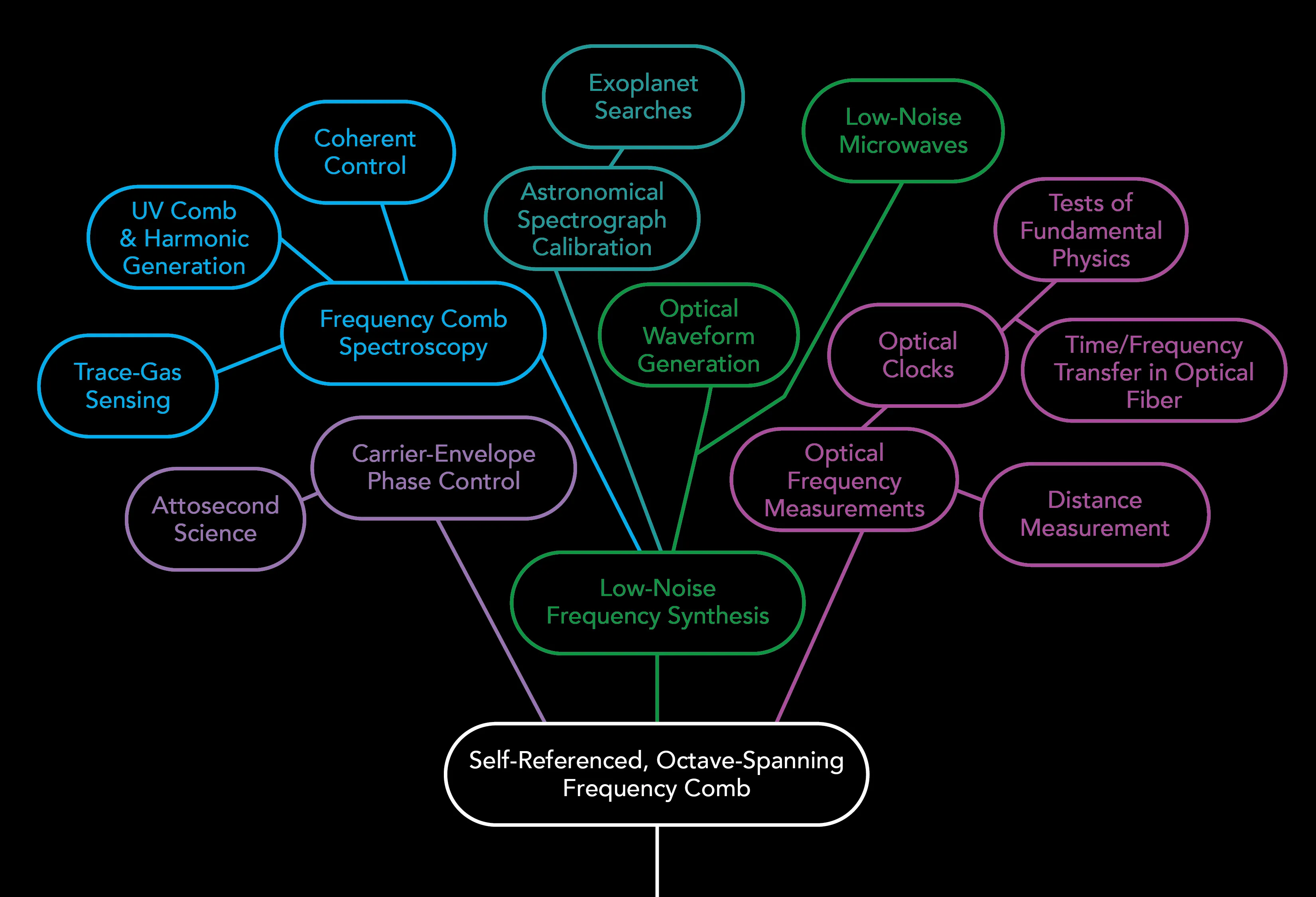
A stabilized, self-referenced optical frequency comb enables incredible applications. These are graphically shown in the figure below, which is adapted from a paper by Scott Diddams et al. (Scott A. Diddams, “The evolving optical frequency comb,” J. Opt. Soc. Am. B. 27(11), B51-B62, 2010).